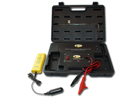
PRO-300 Valve & Wire Locator
The all NEW Pro-300 ResiTracker Residential Wire and Valve Locator is the perfect fit for the contractor working primarily with smaller wired systems. Operationally, it sets up and acts just like the bigger Pro700. At half the power output, can save without being left short on performance.
How to Use the Armada Pro300
Wire and Valve Locator
-
Install the Batteries in the Transmitter
The Pro300 transmitter uses eight "C" cell alkaline batteries. To install the batteries, open the transmitter case. The battery compartment is located at the upper center area of the transmitter. Remove the five holding screws and open the battery compartment. Orient the batteries according to positive and negative polarity, and put the batteries in the compartment. Replace the battery cover.
-
Test the Transmitter
Turn on the transmitter. The power switch is located on the front of the unit. There is a red LED on the upper front part of the transmitter. When the batteries are installed and the unit is ready, the red light will blink dimly. If not, adjust the batteries. Be sure the polarities are correct and the connection is good. If nothing happens, check that the batteries new and fully charged.
-
Install the Battery in the Receiver
The receiver uses one 9v alkaline battery. The battery compartment is on the back of the Pro300 receiver. Remove the battery compartment cover, and install the battery, taking care to properly connect the positive and negative terminals. Replace the cover.
-
Connect the Red Wire
On the controller, disconnect the common wire, as well as the station wire of the valve to be traced. With the transmitter off, connect the red lead to either the common wire or the station wire.
-
Connect the Black Wire
Connect the black lead to the ground stake. Insert the ground stake into the soil outside. Never connect wires to the clock, as this can cause damage to the clock. Do not use common grounds, such as pipes or electrical grounds. The ground stake must be placed in earth, and must be independent of the sprinkler system itself. Otherwise, the Pro300 will not work properly.
-
Test the Connections
Turn on the transmitter. Now, the LED should blink brightly. The better the ground connection, the brighter the light will blink. A good ground is important for effective sprinkler system valve locating.
Soil conditions affect the unit's ability to find lost valves. Moist soil is better for conductivity. Dry, sandy soil can make grounding more difficult. If desired, moisten the grounding area.
|

- Adjust the Settings
After connecting and testing the Pro300 transmitter, turn on the receiver. The volume knob on the side of the receiver controls the power. Put the receiver near the operating Pro300 transmitter. If the receiver is working properly, it emits a beeping sound. A high-pitched tone means that the user is too close to the receiver, or that the batteries are low. A fading signal also indicates low batteries.
Adjust the signal volume using the volume knob on the side of the receiver. With both the receiver and transmitter powered on, let the receiver antenna dangle a few inches above the ground. Move it gently from side to side. Listen for a beeping signal. The closer the receiver comes to the cable, the louder the signal will be.
-
The Null Principle
The Pro300 can find irrigation valves by operating on the null principle. To the left and right of the cable, the receiver emits a steady signal. Directly above the cable, the signal disappears. This is the null, or absence of signal.
By following the null, the user can trace the wire or cable directly to the buried valves. Too high a volume will overpower the null signal. If the null is not apparent, turn the volume down.
-
Finding Solenoids and Valves
Each valve controls a specific zone of the lawn sprinkler system. A wire connects from the valve to the controller. Ideally, the zones are marked on the controller or on the wires themselves. Determine which wire connects to the valve to be located.
Using the null principle, follow the wire. When the unit finds the irrigation valve location, the signal expands into an area about two to four feet in diameter. This indicates the presence of an underground valve or solenoid. Unless the wire connects to other valves further on, the signal will end here. In some cases, one might continue past the first valve, to locate other valves if they are on the same wire. Dig carefully to unearth the valve box and the underground valves.
-
Finding Wire Faults or Damage
The Pro300 can also locate wire breaks or damaged wiring. Set up the unit, as above. The difference is in the reception of the signal. A break in the wire causes the signal to stop at the point of the break. Damage to the wire causes a drop in signal, but the signal will not necessarily stop. Minor damage does not produce enough of a response, and cannot be located with the Pro300. Practice and experience will help the user to operate the unit to maximum effect. If the LED light is weak or absent, be sure the cable or wire is properly grounded. If the signal can't return to the ground stake, the location attempt will fail.
|