PRO-700 Valve & Wire Locator
The NEW Armada Pro 700 Wire Finder and Sprinkler Valve Wire Tracker
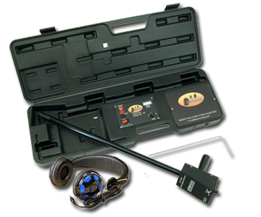
finds and tracks irrigation wiring, valves, and wiring faults. Lightweight, the Pro700 comes complete the Pro700R Receiver, Pro700T transmitter/Carrying Case, Pro700ST Ground Stake, and User Guide.
The Pro-700 Wire and Sprinkler Valve Wire Tracker is a new irrigation tester for irrigation contractors and sprinkler maintenance personnel. Incorporating a powerful transmitter and sensitive receiver, the Pro700 tracks irrigation wires, finds missing sprinkler valves, and detects damage to vulnerable underground cabling. The Pro700 transmits an easy to follow beeping signal that is tracked by the extra long receiver. Simply connect the transmitter to ground and the wire to be tracked and turn it on. Follow the beeps with the receiver using the visual meter, external speaker, or a headset. It is that simple.
The Pro700 incorporates many features not found on ordinary, outdated models. The Pro700 has a 27 inch receiver, avoiding the need to bend over to track wires. An external speaker is standard, but a headset is included if a user prefers. Standard “D” batteries power the transmitter, making replacement simple. An advanced electronic circuitry provides 60hz buzz rejection or cancellation, for a clearer, cleaner sound.
How to use the PRO-700
Valve & Wire Locator
- Install the Transmitter Batteries
The Pro700 uses eight "D" cell batteries. Open the transmitter case. The battery cover is located at the right-hand side of the transmitter unit. With the unit off, remove the two holding screws on the battery cover.
Orient the batteries according to positive and negative polarity, and place the batteries in the holder. Once the batteries are installed, replace the cover and turn on the unit. The red power switch is located on the front of the transmitter.
- Test the batteries
To test the batteries, push the red battery test button. A successful battery installation returns a reading of 8 or higher on the analog meter. If there is a poor response, or no response at all, adjust the batteries to ensure a good connection. If still no response, be sure the batteries are good. For best results, use new, fully-charged batteries.
- Install the 9v Battery in the Receiver
Turn the Pro700 receiver over to locate the battery compartment. Remove the two holding screws and lift the battery compartment cover. Connect the positive and negative terminals to the 9v battery, and place the battery in the compartment. Replace the cover and screws. Turn the unit on. Push the red battery test button on the underside of the Pro700R receiver. If the connection works, the analog needle on top of the receiver will move to the right, to an optimal reading of 10. If this doesn't happen, check the battery.
- Connect the Red Wire
Warning - when the power is on, never touch the red and black clips connecting the transmitter to the cable. Touching the clips can result in serious injury or death. The controller, or timer, has several stations. Each station has a wire connecting to a different valve. Each valve is responsible for one zone of the sprinkler system. On the controller, find the wire leading to the desired zone valve. Disconnect this wire. As well, disconnect the common wire. With the transmitter OFF, plug the red lead into the red outlet on the transmitter. Connect the red lead to the wire to be traced.
- Connect the Black (Ground) Wire
Plug the black lead into the black outlet on the transmitter. Clip the other end to the ground stake. The ground stake must be inserted into the earth or soil. Never connect wires to the clock, and never use common grounds such as pipes or electrical grounds. The ground stake must be inserted into soil, independent of the rest of the system. Otherwise, the valve locator will not work properly.
If the controller is inside, it may be necessary to run an extension wire from the black lead to the ground stake. Use a length of insulated copper wire. On the extension wire, strip the insulation casing from the ends, leaving up to two inches of exposed wire. Clip the black lead to one end. Wrap the other end around the ground stake, and insert the ground stake into the soil outside. Be sure to push the ground stake all the way into the earth.
- Test the Transmitter
Turn on the Pro700 transmitter. Increase power until a reading between 4 and 8 appears. If the reading doesn't register above four, turn the unit off. Retry Step #5, above. Poor grounding may be the result of soil conditions. Moist, earthy soil has better conductivity than dry, sandy soil. Moisten the grounding area if necessary. If results are consistently below four, re-test the batteries and replace if necessary.
|
Stop! Playing hide and seek...
|
- Test the Receiver
 The power and volume knob is on the frontof the Pro700 receiver. Turn on the receiver. Make sure the transmitter unit is also powered on. Bring the receiver near the Pro700 transmitter. The receiver is working properly if it emits a beeping sound. A high-pitched tone means the user is too close to the receiver, or that the batteries are low. A fading signal is also a sign of low battery power. The power and volume knob is on the frontof the Pro700 receiver. Turn on the receiver. Make sure the transmitter unit is also powered on. Bring the receiver near the Pro700 transmitter. The receiver is working properly if it emits a beeping sound. A high-pitched tone means the user is too close to the receiver, or that the batteries are low. A fading signal is also a sign of low battery power.
The receiver comes with optional headphones, but it also has an external speaker. The headphone jack is on the underside of the receiver. The volume control regulates the loudness of headphones and/or the speaker. The analog meter, on the front of the receiver, shows the reception strength of the signal.
- The Null Principle
Make sure the transmitter and receiver are both on. Point the receiver toward the ground, and sweep the unit gently from side to side. Listen for the beeping sound. To the immediate right and left of the cable, the signal increases in volume. However, once the receiver is directly over the wire, it returns almost no sound at all. This is the null principle. The null is an absence of signal.
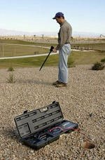
- Lawn Sprinkler System Valve Location
To locate irrigation valves, follow the null. Begin where the wire enters the ground. When nearing a valve or solenoid, the audible signal expands into an area roughly two to four feet in diameter. Since this is the irrigation valve location, the signal will usually not continue past this area. Sometimes, the cable may lead to more valves further on. If necessary, continue past the first valve to check whether other valves are also located on the wire.
- Finding Wire Faults or Damaged Wire
The Pro700 also locates wire breaks or severe wire damage. Set up the unit as if tracing wire to find lost valves. Do not adjust the receiver level above 10. A drop in signal level may not be apparent if the meter reads over 10, or is pegged hard to the right.
A traced wire will emit a signal along the entire path of the cable. In the case of a break, the signal will stop at the break. A nick or damage to the wire will cause an audible drop in the signal level. The analog meter on the receiver will also show a drop in signal level. The more damage to the wire, the more the signal will drop. With practice and expertise, even small nicks in wiring can be located.
Note: slack loops of wire, left underground during installation, can cause an increase in signal even if there is no damage to the wires.
- Finding the Depth of a Wire
First, locate the path of the wire. Mark the ground above the path. Stand to the left or right of the path. Hold the receiver at a 45-degree angle, pointing toward the wire. Move the receiver slightly to find the angle that returns a null signal. Make a mark at the spot. The distance between the two marks is the approximate depth of the wire.
|